■Ideal standard of mechanical 3D-CAD 10 years from now
REV:2019.04.23-1
1.Introduction
I got a job at a tire manufacturer group company in 1981, and have been engaged in tire manufacturing equipment and tooling design, quality control and sales for 38 years.
After introducing 2D-CAD me10 (made by Hewlett Packard) in 1987, I customized it.
Based on that experience and the result of operating 3D-CAD Fusion 360 (made by Autodesk), I considered A vision of mechanical 3D-CAD 10 years from now.
2.Problems of current 3D-CAD including examples of operation results of Fusion 360 (based on me10 customization experience)
(1)Confirmation of rack and pinion operation
△Please check with the play button on the video.
○Problem
①In the case of contact restraint, calculation load is high and slow.
There may be cases where left-right synchronization failure occurs due to an error due to increased calculation load.
②Joint constraints with low internal calculation load do not have left / right synchronization function.
(2)Confirmation of operation of synchronization pin
Explanation of operation of synchronization pin (see the figure below)
B2 (boss 2) is fixed to S (shaft) by P (synchronization pin).
B1 (boss 1) slides Xst to the right, and the end face hits B2 and pushes B2.
At that time, C (Countersink) of B1 is right above P.
P moves upward with the taper of C (Countersink) of S. (Yst)
With B1 and B2 linked to P, move to the right together. (Zst)
○Problem
①It did not move by contact restraint.
②Joint constraints with low internal calculation load do not have move in order function.
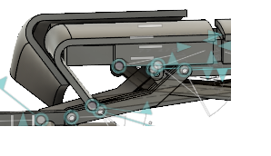
(3)Confirmation of operation of link mechanism and link dimension change simulation
Inventor: Masaji Mori, Japan Patent Kokai S50-148485 (1975.11.28). I confirmed this patent as a model.
※Because it was not possible to synchronize the left and right by the rack and pinion, it was substituted by the virtual slide joint.
※Because it was not possible to motion order control by synchronization pin, it corresponds by motion study setting.
△Please check with the play button on the video.
・I changed link dimensions in sketch editing ,and repeated motion analysis then confirmed collision avoidance.
○Problem
①It is necessary to repeat the same operation many times in confirmation after changing link dimensions.
(Operation position specification to check. Clearance dimension check at that time)
(4)Commercially available 3D-CAD catalog
Example: Take in Kakuta toggle clamp 3D-CAD data from Osaka kakuta Kogyo Co., Ltd. in STEP.
Joint restraint setting because there is no joint restraint
△Please check with the play button on the video.
○Problem
①Joint constraints are not attached to commercially available 3D-CAD data, joint constraint setting is required each time
(5)Reasons why 2D-CAD is not lost at present and can not be completely transferred to 3D-CAD.
①Parts production at this time except for 3D printer production and mold digging part processing, a large process (casting, welding structure, press production, etc.) is decided by 2D drawing information, and each process worker makes it while looking at dimensional tolerances, geometric tolerances, surface roughness, and other notes of faces described in 2D drawings.
There is no such information in 3D-CAD at present, and there is no standardization even if there is a part.
(6)What can not be done with current 3D CAD analysis
①In the 3D-CAD motion analysis at the present time, the friction is 0, and no analysis considering the friction in the real world has been made.
3.Ideal standard of mechanical 3D-CAD 10 years from now
【Problem Solution of 2.(3)①】
(1)Prepare a macro language that machine design engineers can use.
It is impossible for machine design engineers to customize using C language or Python.
My hope is high level language of me10 macro language level
・Interpreter, BASIC like, 1 Drawing (action) 1 command, Manuals are in place,
echo function (command history), trace function (command + variable history),
external command (OS command, BAT, EXE) remote execution function (variable and result via files), etc.
【Problem Solution of 2.(1)①、②、(2)①、②、(4)①】
(2)Advancement of motion constraints and standardization at the kernel level.
(Right-and-left synchronization, Move in order ,thread pitch, etc. Calculation load is heavy and error-prone contact constraint calculation is reduced.
Contact constraint is used only in limited cases such as motion confirmation by gear clearance)
【Problem Solution of 2.(5)①、(6)①】
(3)Profiles of surface dimensional tolerance, geometric tolerance, surface roughness, coefficient of friction, notes,etc .: Perform standardization at kernel level.
Only the required numbers are registered and the default is not entered.
→This will realize the future disused of 2D-CAD.
→As a result, more advanced analysis such as motion analysis including friction, interference check with dimensional tolerances,
and motion analysis of play by clearance will be realized.
4.Finally
This study is a summary of what mechanical equipment designers who have been engaged for many years feel that they are lacking for the current 3D-CAD.
For mechanical CAD developers, please confirm the voice of CAD users including this consideration, and ask for the determination and standardization of the future direction of CAD development.
For goal: "Complete mechanical 3D-CAD more efficiently."